Magnetic Level Indicators vs. Gauge Glass: Understanding the Differences for ASME Section I Applications
by Jordan Bunting, Chief Technology Manager
When specifying water level measurement systems for ASME Section I boilers, engineers often face confusion about the roles and requirements of magnetic level indicators versus traditional gauge glass. While both technologies serve the critical function of monitoring boiler water levels, they operate under fundamentally different principles and have distinct regulatory classifications that directly impact their application in steam boiler systems.
Understanding these differences is essential for ensuring code compliance, maintaining plant safety, and making informed decisions about level measurement investments. And the distinction goes far beyond simple technology preferences. It affects system design, installation requirements, and operational safety protocols as well.
Fundamental Technology Differences
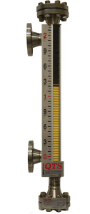
Gauge glass operates on the principle of direct visual indication. Operators can physically see the water line through transparent materials, whether using reflex, transparent, or ported bi-color designs.
This direct reading capability provides immediate, unmistakable visual confirmation of water level without requiring interpretation or electronic systems.
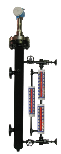
Magnetic level indicators function through magnetic coupling. By comparison, a magnetic float travels within a sealed chamber, and its position is indicated externally through magnetic interaction with flag indicators or electronic transmitters.
The water level is indicated through the pipe wall rather than direct visual contact with the process fluid.
This fundamental difference in operating principles has led ASME Section I to classify these technologies in distinct categories, each with specific code requirements and limitations.
Technology Comparison: Differences Between Gauge Glass and Magnetic Level Indicators
Here’s a quick reference guide for the differences between these two technologies:
| Feature | Gauge Glass | Magnetic Level Indicator |
| Reading Method | Direct visual through transparent material | Magnetic coupling through pipe wall |
| ASME Classification | Direct reading level measurement | Water level sensing device |
| Code Requirement | Mandatory on all Section I boilers | Optional/supplementary |
| Operator View | Actual water line visible | Flag indicators show level position |
| Remote Capability | Local indication only | Can provide remote indication |
| Pressure Limitation | No specific ASME limit | 900 PSI MAWP for remote use |
ASME Code Classifications and Implications
Under ASME Section I, magnetic level indicators are categorized as “water level sensing devices,” while gauge glass maintains its traditional classification as direct reading level measurement.
This distinction carries significant regulatory implications that affect how each technology can be applied.
Gauge glass retains its status as the gold standard for local level indication in boiler applications. The code specifically requires gauge glass installation on all Section I boilers, recognizing its direct reading capability as essential for operator safety.
The immediate visual confirmation provided by gauge glass cannot be replaced by magnetic coupling technology, regardless of the magnetic system’s accuracy or reliability.
Magnetic level indicators, while valuable, cannot substitute for code-required gauge glass. This represents one of the most critical misunderstandings in the industry.
Plant operators sometimes assume that installing a magnetic level indicator eliminates the need for gauge glass. However, ASME Section I explicitly prohibits this substitution.
The magnetic level indicator serves as a complementary technology, not a replacement.
When Each Technology is Required
For boilers rated at 400 PSI MAWP or less, ASME Section I requires one gauge glass as the minimum configuration. However, magnetic level indicators can be added as secondary visual local level indicators, provided they meet all applicable code requirements.
For boilers above 400 PSI MAWP, the code mandates either two gauge glasses or one gauge glass plus two independent remote level indicators.
Magnetic level indicators can serve as remote level indicators, but only up to 900 PSI MAWP and only when equipped with appropriate transmitters for control room display.
This tiered approach reflects the increased safety requirements for higher pressure applications while acknowledging the practical limitations of different measurement technologies.
ASME Section I Requirements by Pressure Rating
| Boiler Pressure | Minimum Requirements | Optional Additions |
| ≤ 400 PSI MAWP | 1 Gauge Glass | Magnetic Level Indicator as secondary visual indicator |
| > 400 PSI MAWP | 2 Gauge Glass OR 1 Gauge Glass + 2 Independent Remote Level Indicators | Magnetic Level Indicator (≤ 900 PSI only) as remote indicator |
Visual Indication Boundaries and Safety Considerations
Both gauge glass and magnetic level indicators must comply with ASME Section I’s rigid requirements for visible indication range. These boundaries ensure that water level readings remain accurate and safe across all operating conditions.
The indication scale cannot encroach within 2 inches (but not more than 3 inches) above the lowest permissible water level as determined by the boiler manufacturer.
Additionally, the indication scale must not interfere with the outer diameter of either the lower water piping or upper steam piping connections.
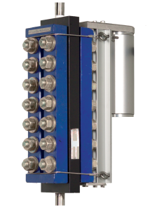
For magnetic level indicators, this translates to reducing the visible range on flag indicators by approximately 4 inches total from the vessel center-to-center measurement—2 inches from the top and 2 inches from the bottom centerline.
This ensures that dangerous water levels cannot be misread as safe operating conditions.
The safety philosophy behind these requirements centers on preventing operators from receiving false indications during dangerous conditions. If the water level drops to a dangerous point, the level indication system should not display readings that could be interpreted as safe operating levels.
Installation and Maintenance Considerations
Gauge glass installation requires careful attention to piping configurations, valve arrangements, and blowdown procedures. The direct connection to process fluid means that gauge glass systems need regular cleaning and potential replacement of glass components. However, the simplicity of direct visual reading eliminates concerns about electronic system failures or calibration drift.
Magnetic level indicator installations involve more complex considerations including float chamber materials, magnetic coupling reliability, and potential sediment buildup within the float travel path. The sealed chamber design provides protection from external environmental factors, but internal maintenance can be more challenging than gauge glass systems.
Both technologies require isolation valves and drain valves per PG-60.1.2, emphasizing the importance of regular blowdown procedures to maintain accurate level indication and remove sediment buildup.
Installation Requirements Comparison
| Requirement | Gauge Glass | Magnetic Level Indicator |
| Process Connection | Per boiler manufacturer specs | 3/4″ NPS minimum |
| Drain Connection | Required per PG-60.1.2 | 1/2″ NPS minimum |
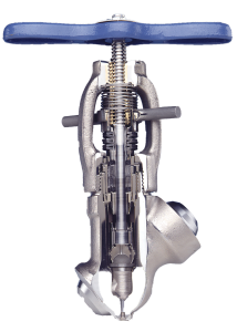
| Isolation Valves | Required | Required |
| Materials | Standard boiler materials | 304L, 316L, Alloy 800, 825, C-276, C-22, Inconel 690, Alloy 59, 625, 600 |
| Indication Range | 2″-3″ above lowest permissible level | 2″-3″ above lowest permissible level |
| Water Column Use | Can be mounted to water column | Cannot be used as water column |
Cost-Benefit Analysis for Plant Operators
Initial investment costs typically favor gauge glass due to its simpler design and fewer components. Magnetic level indicators require additional hardware including the float chamber, magnetic coupling system, and potentially electronic transmitters for remote indication capabilities.
Long-term operational costs present a different picture. Gauge glass requires regular replacement of glass components and more frequent maintenance due to direct process fluid exposure. Magnetic level indicators, when properly specified with appropriate materials, can provide longer service life in challenging process conditions.
Operational benefits of magnetic level indicators include improved visibility from greater distances, reduced operator exposure to high-temperature/high-pressure systems during level checks, and the ability to integrate with control systems for remote monitoring. However, these benefits must be weighed against the code requirement to maintain gauge glass as the primary local indication.
Cost-Benefit Quick Reference
| Factor | Gauge Glass | Magnetic Level Indicator |
| Initial Cost | Lower | Higher |
| Installation Complexity | Simple | More complex |
| Maintenance Frequency | Higher (glass replacement) | Lower (sealed system) |
| Operational Safety | Direct visual confirmation | Remote monitoring capability |
| Integration Options | Limited | Control system compatible |
| Service Life | Shorter (replaceable components) | Longer (proper materials) |
| Code Compliance | Mandatory | Supplementary only |
Making the Right Choice for Your Application
You shouldn’t have to choose between gauge glass and magnetic level indicators. While ASME Section I requires gauge glass, magnetic level indicators are a complementary technology that enhances measurement precision and plant safety.
The real decision involves determining whether the additional benefits of magnetic level indicators justify the extra investment for your specific application.
Consider magnetic level indicators when remote monitoring capabilities, enhanced operator safety, or integration with control systems provide operational value that exceeds the additional cost.
However, remember that these benefits supplement rather than replace the fundamental safety provided by direct reading gauge glass.
Understanding these critical differences ensures both code compliance and optimal safety in your ASME Section I boiler operations, while avoiding costly specification errors that could compromise plant safety and regulatory compliance.