11 Magnetic Level Indicator Design & Code Rules for ASME Section I Boilers
By: Jordan Bunting, Chief Technology Manager
When specifying magnetic level indicators for ASME Section I boiler applications, compliance with specific design and code rules is non-negotiable. These regulations ensure safe operation and regulatory compliance in steam boiler systems. Here are the 11 essential rules every engineer must follow.
1. Follow Core ASME Requirements
Magnetic level indicators must comply with requirements outlined in PG-12.2, PG-12.3, and PG-60 subsections of ASME Section I. These sections govern the fundamental design, materials, and installation standards for all boiler level instrumentation.
2. Use Only Approved Float Chamber Materials
The float chamber must be constructed from one of these ASME-approved materials:
- 304L Stainless Steel
- 316L Stainless Steel
- Alloy 800
- Alloy 20
- Alloy 825
- C-276 (Hastelloy)
- C-22 (Hastelloy)
- Inconel 690
- Alloy 59
- Alloy 625
- Alloy 600
These materials are specifically chosen for their corrosion resistance and performance in high-temperature, high-pressure boiler environments.
3. Match Pressure Rating to Material Grade
The float chamber pressure rating must correspond to the selected material grade from the approved list above. This ensures structural integrity under operating conditions and meets ASME pressure vessel requirements.
4. Meet Minimum Connection Size Requirements
ASME Section I mandates specific connection sizes:
- Process connection: 3/4″ NPS minimum
- Drain connection: 1/2″ NPS minimum
These sizes ensure adequate flow rates for proper level indication and maintenance procedures.
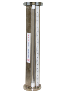
5. Comply with Indication Range Boundaries
ASME Section I code has rigid requirements for visible indication range in relation to the lowest permissible water level and the water/steam piping from the boiler.
The lowest permissible water level is set by the boiler manufacturer and is the lowest level point before a dangerous condition is present during operation. The indication scale cannot encroach within 2” and not more than 3” above the lowest permissible water level.
In addition, the indication scale must not encroach within the OD of the lower water piping and the OD of the upper steam piping. An easy approach is to deduct 4” total (2” top + 2” bottom) from the Vessel C-C to determine the indication range, provided all other requirements are met.
ASME Code Rules & Best Practice
- #3 must be positioned no closer than 2” and not more than 3” above #4.
- #2 cannot be positioned above #1.
- #3 cannot be positioned below #5.
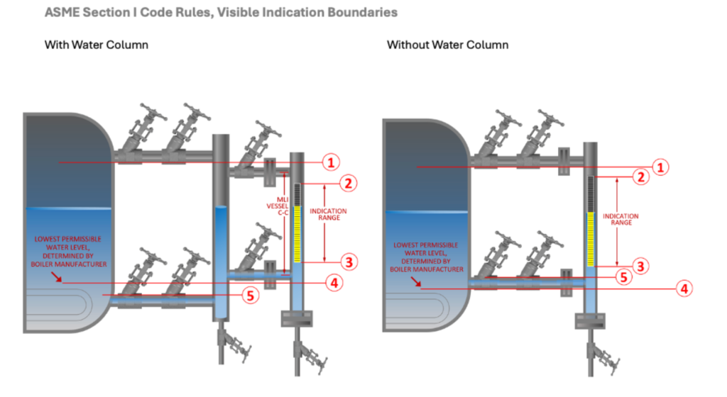
Diagram Key:
- Outer edge of steam piping.
- The highest visible point on the water level indicator.
- The lowest visible point on the water level indicator.
- Lowest permissible water level, as determined by the boiler manufacturer
- Outer edge of the water piping.
Best Practice: Reduce visible range on flag indicator by 4” total from Vessel C-C, (2” top + 2” bottom from CL)
6. Observe the 900 PSI MAWP Limitation for Remote Applications
Magnetic level indicators cannot function as remote level indicators above 900 PSI MAWP. This limitation addresses accuracy concerns during pressure cycling and reliability issues with magnetic floats in stagnant applications prone to sediment buildup.
7. Cannot Replace Code-Required Gage Glass
Magnetic level indicators are supplementary, not replacement devices. The required gauge glass provides direct visual reading where operators can see the actual water line, while magnetic gauges indicate level through magnetic coupling across the pipe wall.
8. Prohibited from Water Column Use
ASME Section I PG-12.3 prohibits using magnetic level indicators as water columns. This means you cannot mount a gage glass directly to a magnetic level gauge. Each component must maintain its independent function and installation.
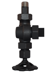
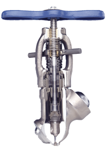
9. Install Required Isolation Valves
Every magnetic level gauge must include isolation valves per PG-60.1.2. These valves enable safe maintenance, testing, and emergency isolation without system shutdown.
10. Include Mandatory Drain Valve
All magnetic level indicators require a drain valve (PG-60.1.2). Regular blow-down procedures are essential for:
- Removing sediment buildup
- Maintaining measurement accuracy
- Ensuring long-term reliability
The drain piping must route to a safe discharge point for blow-down water, steam, and accumulated sediment.
11. Separate Remote and Control Functions
Remote level indicators cannot serve control purposes (Interpretation I-25-05, July 2025). Level transmitters used for control must be dedicated exclusively to control functions, maintaining clear separation between indication and control systems.
Ensuring Compliance Success
Following these 11 rules ensures your magnetic level indicator installation meets ASME Section I requirements while providing reliable, safe boiler water level measurement. For complex applications or specific code interpretations, consult with experienced level measurement specialists.
At Questtec Solutions, our “BC” model code option simplifies boiler code compliance by incorporating all required materials and ratings per PG-12.3 specifications. Contact our engineering team for application-specific guidance on your next ASME Section I boiler project.